
 Set for Student Project
 Lecture Note
 Lecture Video
 Activity
 Assignment
 Design Project
 Quiz & Exam

Preparing Revit Files for Laser Cutting: A Practical Guide to Flawless Fabrication

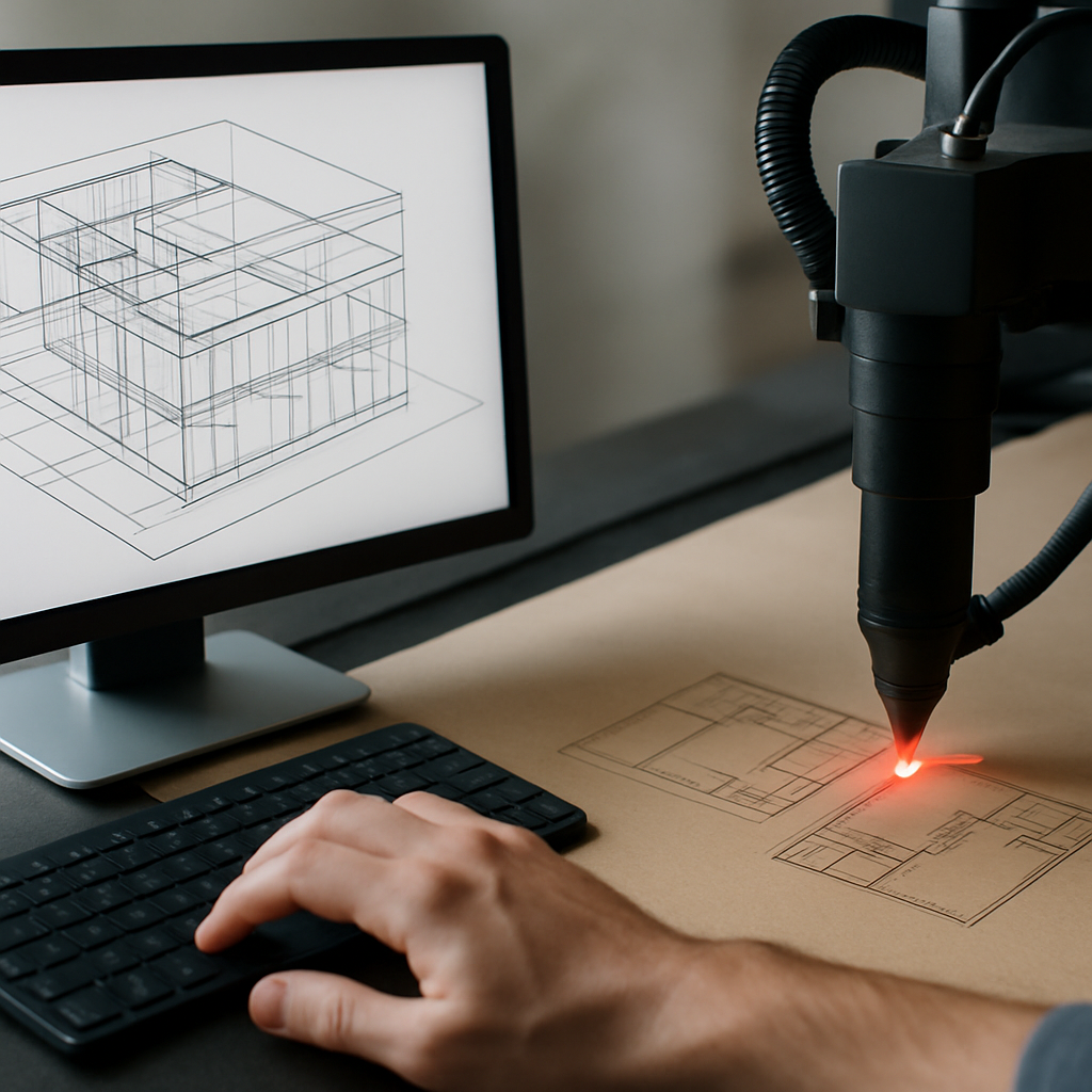
Why Careful Revit Preparation Is Your Laser Cutting Superpower
Prepping Revit files for laser cutting isn’t just a matter of hitting “export” and hoping for the best. It’s about transforming your digital designs into tangible, laser-cut pieces—with accuracy, intention, and zero guesswork. Whether you’re an architect eager to craft a precise scale model, or a designer tinkering with prototypes, how you handle your Revit files directly impacts your fabrication results. This guide is here to walk you through a clear, beginner-friendly process for getting Revit projects laser ready, steering you around the classic pitfalls that even seasoned pros sometimes stumble into. We’ll dive into a practical workflow, pass along some real-world tips, and help you confidently bridge that sometimes-tricky gap between digital and physical creation.
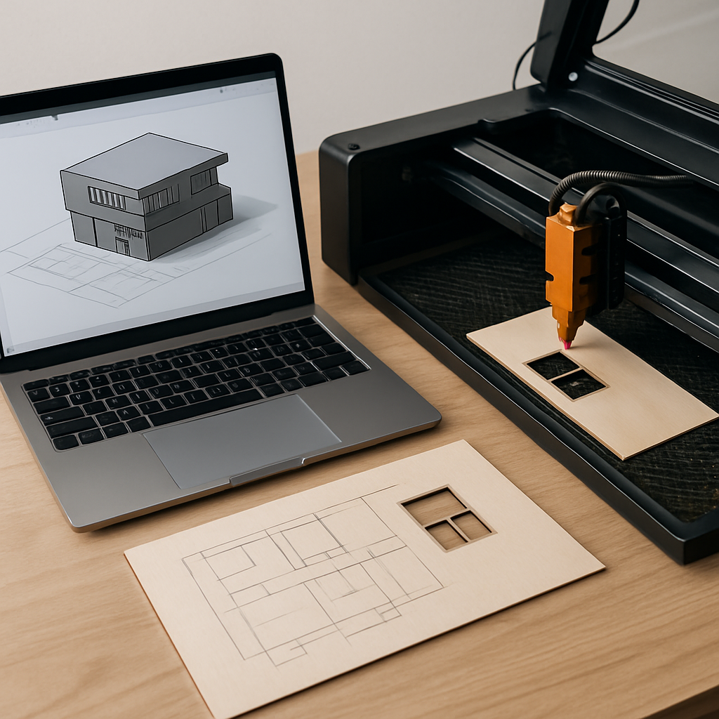
Getting laser cutting right actually starts with a mental reset: you aren’t just drafting a drawing—you’re creating a set of instructions for a machine that’s ruthlessly literal. Unlike 3D printers, laser cutters don’t forgive ambiguity. Every line or curve in your file turns into a real mark or cut on your chosen material. Overlook a line type, mess up your scale, or misassign a layer, and you could waste materials, lose hours, or completely tank your project. Investing some time upfront to prep your Revit files gives you a serious superpower: the ability to predict—and control—exactly how your concept leaps from screen to reality.
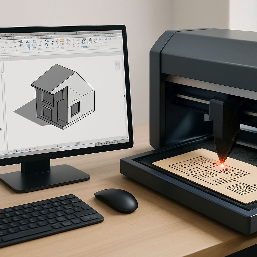
Take, for instance, an architectural model built from acrylic sheets. If you rush the export, you might find yourself with panels that have missing outlines, misaligned joints, or tabs that simply don’t fit together. But a carefully prepped Revit file anticipates all of that, making sure each part not only reflects your design but also assembles smoothly and reliably. That extra prep work lets you guide your project from digital sketch to finished object—giving you better results, less rework, and a lot fewer headaches along the way.
Understanding the Gap: What Laser Cutters Need vs. What Revit Gives You
Revit is a superstar when it comes to 3D modeling—especially in architecture and engineering. But here’s the rub: laser cutters don’t care about 3D models, no matter how gorgeous. What they want is simple, clean, flat 2D vectors, usually in a file format like DXF or SVG. And there’s your first hurdle. Revit’s built-in export tools are aimed at construction documentation, not fabrication. So your job is to thoughtfully translate all that rich Revit data into crisp, unambiguous lines that the laser can follow. That’s not just a quick “print to file”—it means extracting the right details, flattening out the geometry, and tidying things up so you’ve got pure cut paths, not just construction drawings.
It’s a common rookie mistake to think a basic plan or elevation will do the trick. But if you go that route, you’ll probably end up with missing layers, stacked lines, or confusing details that the laser simply can’t cut. You’ve really got to put yourself in the shoes of the fabricator: focus on outlines, not volumes. Ask yourself—if you handed this file to someone who didn’t know your project, would they instantly know what to cut, what to engrave, and what to ignore?
Let’s say you’re exporting a detailed screen pattern from Revit. In the model, the latticework looks amazing, but if your exported view includes shadows, hatches, or stray construction lines, the laser will think they’re all cut paths. That can lead to disasters like double-cut lines that weaken the material, or random lines that wreck your beautiful pattern. On the flip side, if you just export an outline and forget the joinery, good luck snapping the pieces together after cutting! The difference between Revit’s construction-first mindset and the laser cutter’s need for clarity isn’t just technical—it’s conceptual. You need to be a translator, reimagining your model as a clear, buildable set of instructions.
And don’t forget: tolerances and detail levels are different in the digital and real worlds. In Revit, you can get away with zero-thickness lines or fuzzy boundaries. But with a laser cutter, every single line becomes a hard edge, a gap, or a join. Knowing how to bridge that gap is crucial—not just to get clean cuts, but to make sure your finished pieces actually fit and function the way you want.
Essential Steps for Adapting Your Revit Files: From 3D Model to Laser-Ready Vectors
When it comes to prepping your files, start with a clear purpose. The first thing you’ll want to do is isolate just the components or assemblies you’re planning to fabricate. In practice, that usually means creating a special 3D view or even a temp working file that strips away everything you don’t need. Use tools like section boxes, filters, or worksets to narrow things down. Remember, unless you’re actually cutting them, the laser doesn’t care about annotations, chairs, or hidden plumbing lines!
Say you’re laser cutting a scale model of a building’s façade. Go ahead and hide all the extra stuff—MEP fixtures, landscaping, interior walls, all of it. Now you’re left with just what needs to be cut. Use Revit’s visibility/graphics overrides to turn off whole categories and subcategories, so your 2D exports are clean and free of visual noise. If you’ve got repeating elements, like window mullions or panels, it’s smart to create a schedule or use view templates to control their look and keep things consistent across all your exported views.
Once you’ve boiled it down to essentials, create 2D views that show each piece as it should be cut. For façades, that might be an elevation view with everything flattened. For furniture or structures, you might need plan views of each part laid out separately. Consistency is huge: use true-to-life scale (1:1), thin line weights, and turn off shadows, fills, and any hatching. Export these views as DWG or DXF files, and check twice that you’ve got the units right—most fabricators want millimeters.
If your assembly has complex shapes, think about “unfolding” or flattening them—kind of like laying out a cardboard box before it’s folded. Revit doesn’t have a one-click unfold feature, but you can either model the parts in their flat state, or use reference planes to guide you as you manually flatten them. Always double-check your export by mentally walking through the assembly—one misplaced tab or flipped piece can really mess things up further down the line.
With your 2D exports in hand, it’s time to jump into a vector editor like AutoCAD or Illustrator. This is where the real magic happens: get rid of duplicate lines, clean up any messy geometry, and assign colors or layers for different cut types (for example, red for cutting all the way through, blue for engraving). This is also when you’ll spot weirdnesses—like lines that don’t connect, invisible elements, or scale mix-ups. Fix it all now before the file ever sees a laser. A little extra time here will save you materials, money, and headaches later.
Picture exporting a puzzle or an interlocking parts model. You’ll often find that Revit’s export spits out broken polylines or duplicates at the seams. In Illustrator, you can use “Join” and “Simplify” to clean up paths; in AutoCAD, the “Overkill” command is perfect for nuking overlapping geometry. Carefully assign your layers or colors to match cut, etch, or score operations—this not only clarifies your wishes, but it helps the fabricator set up the machine settings on their end (and some shops automate this!).
Before you hit send, do a “dry run” by overlaying your vector file onto a grid or a scaled image of your material sheet. This sanity check is gold: it’ll help you spot misaligned parts, missing outlines, or pieces that just won’t fit within the laser bed. It’s also a golden opportunity to optimize your nesting and get the most out of your material—keeping both waste and costs down.
Common Pitfalls: Avoiding Errors That Sabotage Your Laser Cutting
Even with the best intentions, it’s easy to slip into some classic traps. Overlapping lines? That’s a big one. Revit’s exports often stack geometry or leave weird artifacts, which can make the laser cut the same spot twice—leading to burnt edges, wasted time, or even ruined parts. Always run your file through an editor to combine or “overkill” those lines, and do a close-up visual check for any sneaky duplicates.
Another all-too-common goof: getting your scale or units wrong. Most laser shops work in millimeters, and it’s dangerously easy to export your file at the wrong scale. If you slip up, your carefully designed parts could be printed out as dollhouse miniatures—or worse, massive sheets that don’t fit the cutter at all. Always double-check your units, and consider including a dimensioned rectangle in the file so the fabricator (and you) can sanity-check it.
Getting the right level of detail is a balancing act. If you strip out too much, your parts lose vital features. But if you leave in too much, the laser might choke on all the info, or the shop software might miss some cuts—or even crash. Simplify curves where you can, and delete any tiny detail that’s smaller than the laser can physically cut. And when in doubt, ask your fabricator for their advice on minimum feature sizes and kerf (the width of the laser cut), so you avoid learning the hard way.
You don’t have to look far for real-world horror stories. An interior designer exports a decorative screen, but misses the units, so the 2-meter screen becomes a comically tiny 2-millimeter sliver. Or a student sends a scale model with overlapping lines everywhere, causing the laser to double-cut each edge—result: brittle, burned pieces and a ruined project. Or maybe a product designer loads up their file with tiny filigree cutouts that are finer than the laser’s kerf, so the parts are either incomplete or shatter when handled. Every one of these headaches could have been prevented by careful review and a quick chat with the fabricator.
One sneaky pitfall is forgetting about the laser’s kerf—the thin slice of material that the laser vaporizes as it cuts. For tight-fitting assemblies, that can mean joints that are either a loose mess or a frustratingly tight fit. Some designers offset their cut lines by half the kerf, or run a test cut on scrap to dial it in. Ignoring kerf will turn your perfectly modeled design into a pile of almost-right pieces.
And watch out for hidden or locked layers in your editing software. If important geometry is lurking on a hidden or locked layer, it won’t get cut—and you might not realize until you’re staring at incomplete parts. Always flatten and audit your vector file before sending, double-checking that every component is visible, unlocked, and marked with the right layer or color.
Best Practices That Set Your Files Apart
Beyond the nuts and bolts, developing a thoughtful workflow pays off big time. Start by naming your parts clearly and keeping your layers organized—skip the cryptic file names and chaotic layers. Group related components, but be sure each cut piece lives on its own distinct layer or color. If your pieces need tabs, slots, or assembly marks, draw them in explicitly. Don’t leave any of this up to guesswork.
For example, label your parts with clear codes like “A1_LeftPanel” or “B2_TabConnector,” and stick to straightforward layer names such as “CUT,” “ENGRAVE,” or “SCORE.” Good organization is a lifesaver in big or collaborative projects, where multiple people might need to access or edit the files. It also makes life easier for the laser operator: they can quickly grasp your intentions and run your job without confusion.
Try out your workflow on a small scale before jumping into a full-on production run. Many designers will laser-cut a few test pieces, tweak their approach, and only then commit to cutting the whole batch. Taking an iterative approach saves you money and stress—especially if you’re working with expensive materials. While you’re at it, document your process. Jot down what works (and what doesn’t)—your future self will be grateful when it’s time to repeat or troubleshoot the job.
Picture this: before cutting an entire architectural model from plywood, you laser a single floor plate or façade piece. Now you can check the fit, tolerances, and how well the parts snap together. A single prototype might reveal that tabs are too tight, slots are out of alignment, or the engraved labels are too faint. Keeping notes—or a digital checklist—of your file prep steps, settings, and any feedback from the shop helps capture lessons and avoid making the same mistakes next time.
And above all, communicate with your fabricator. Share your intentions, ask them to look over your file, and stay open to feedback. Nobody gets it perfect the first time, and most shops appreciate it when clients actively care about the end result. The best laser cut projects come from collaboration, not just dropped-off files.
Don’t be shy about asking your fabricator what file format, color coding, or settings their machines prefer. Sending along a PDF preview or an annotated version of your drawing can help clarify your intent and prevent misunderstandings. Most shops are happy to do a quick file check or make minor tweaks if you reach out early and communicate clearly. This kind of teamwork not only leads to better results—it also lays the groundwork for good working relationships down the road.
Leveling Up: Tips for Advanced and Large-Scale Projects
If you find yourself regularly prepping Revit files for laser cutting, it’s worth looking into automation and plug-ins. There are add-ons for Revit that can streamline your 2D exports, batch process multiple views, or even help you unwrap complex geometry into flat, laser-ready pieces. Tools like Dynamo or custom families can bake in laser-friendly details right in your Revit model, so you do less manual cleanup later.
Take, for example, specialized plug-ins or Dynamo scripts—they can process a whole group of views at once, saving you hours of repetitive work. If you’re often designing panel systems, you might even develop a custom family template with built-in slots, tabs, and layer assignments, making it possible to export laser-ready geometry as part of your regular modeling. Some advanced users even have Dynamo scripts offset their cut lines for kerf compensation, or automatically nest parts to fit within a standard material sheet.
For larger assemblies, material efficiency and assembly logic become even more important. Nest your parts tightly on standard sheet sizes, keep waste to a minimum, and add labels or etched assembly info right onto the pieces. When you’re cutting hundreds of components, even a modest 5% material savings adds up quickly. And remember, every extra cut costs both time and money—clean, well-organized files mean faster and cheaper fabrication.
There are even dedicated nesting programs, like DeepNest or RhinoNest, that can automatically rearrange your parts for maximum material yield, slashing offcuts and costs. For especially intricate assemblies, consider engraving tiny part numbers or assembly guides right on the pieces—this can make construction faster and save you from mixing up parts. For large jobs, an illustrated assembly manual that references those markings can be a game-changer, especially if you’re handing off the build to someone else.
Don’t be afraid to push the envelope a little. Try mixing cutting, engraving, and scoring, or experiment with multi-layered builds that really showcase the laser’s capabilities. Prepping Revit files for laser cutting is equal parts technical skill and creative play. The more you try, the more you’ll discover—sometimes the best ideas come from happy accidents, or by just seeing what’s possible at the edge of your tools’ limits.
Think about combining materials—maybe layering wood, acrylic, and paper, or engraving fine textures, or scoring fold lines for crisp paper models. Advanced users love playing with things like living hinges, layered reliefs, or kinetic models that snap together right out of the laser bed. All of these start with careful file prep in Revit, but the end results are unique, functional, and seriously impressive.
At the end of the day, mastering the art of prepping Revit files for laser cutting is about a lot more than just technical know-how. It’s about developing a thoughtful, checked, and creative process—one that lets you confidently turn digital dreams into physical objects. When you know both the strengths and quirks of your tools, you set yourself up to bring your ideas to life with accuracy, style, and a whole lot less stress.


