
 Set for Student Project
 Lecture Note
 Lecture Video
 Activity
 Assignment
 Design Project
 Quiz & Exam

From Screen to Reality: Essential Tips for Turning Your Revit Model into a Physical Model

Why Transform a Revit Model into a Physical Model?
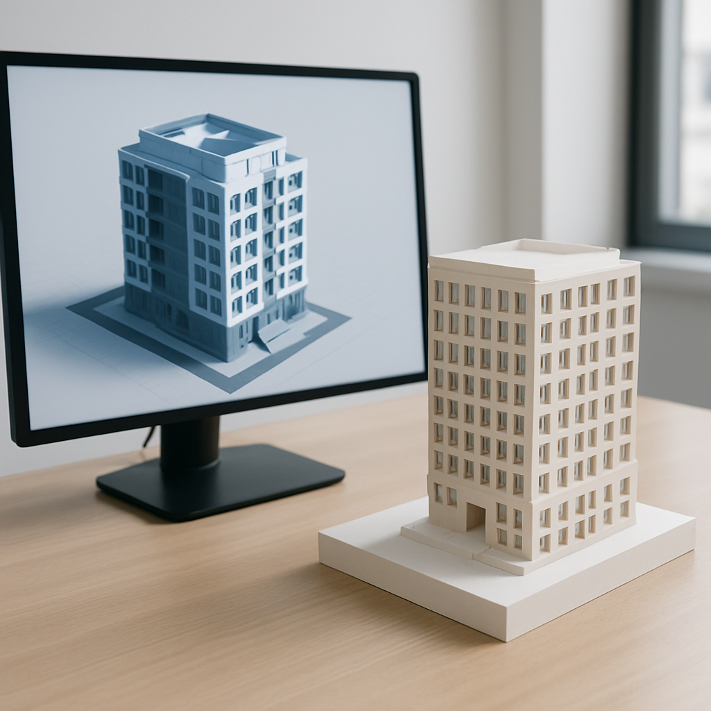
If you’ve ever poured your heart (and plenty of late nights) into a Revit model, you know that rush of finally seeing your digital design pop on screen. It’s pretty satisfying, right? But there’s something almost magical about taking that virtual creation and turning it into an actual, tangible object. Suddenly, your design isn’t just an idea or a collection of lines and surfaces—it becomes something you can pick up, turn over in your hands, and really experience. That shift isn’t just cool; it completely changes the way people engage with your work. Whether you’re presenting to a client, prepping for a nerve-wracking design critique, or just hashing things out with your own team, being able to turn a Revit model into a physical model bridges the gap between vision and reality like nothing else.
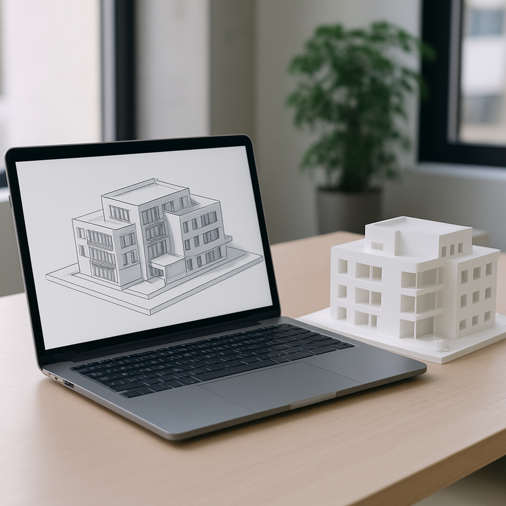
Sure, digital design is powerful—it lets you experiment, tweak, and perfect every last detail. But at the end of the day, physical models speak a universal language. There’s no need for specialized software or architectural jargon; people just get it. Put a model on the table, and suddenly everyone’s leaning in, pointing out details, and asking questions you might never have anticipated. Plus, the process often exposes tiny design issues you’d miss on-screen and can spark creative solutions you wouldn’t have thought of otherwise. Of course, making this leap from digital to physical comes with its own set of hurdles. It’s not as simple as clicking “print” and waiting for a model to materialize—you’ll need to plan ahead, choose your materials and methods wisely, and really think about what you want your model to say.
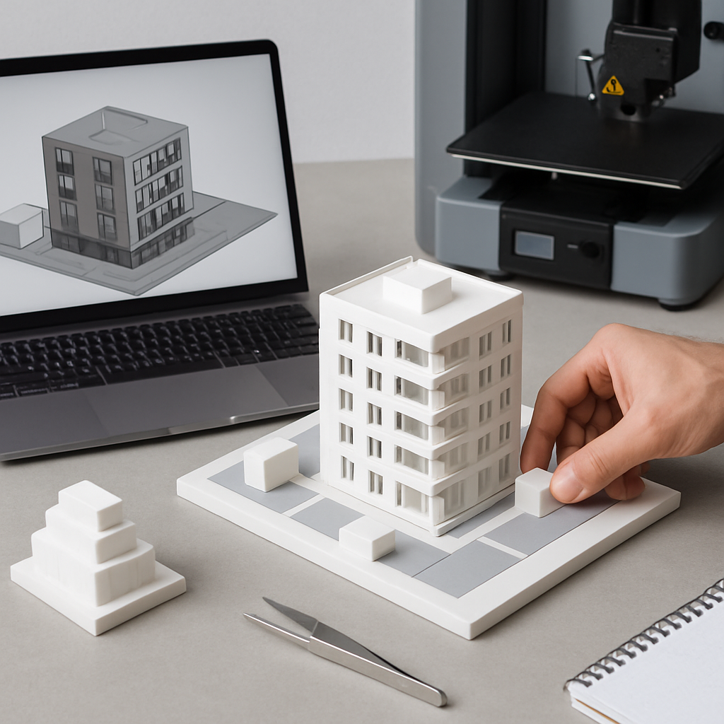
Think about how different a pitch meeting feels when you walk in with a physical model. Digital renderings might look impressive, but they can be abstract or intimidating for clients who aren’t used to reading plans. Set down a tangible model, and suddenly they’re able to grasp scale, see how the building fits onto a site, imagine how daylight will play across the surfaces, or understand how volumes relate to each other. Physical models are also fantastic for testing ideas on the fly: maybe you quickly swap out façade treatments, restack forms, or invite a collaborator to move things around right in front of you. In a classroom, professors rely on models to help students understand space, volume, and composition in a way that’s just not possible on a flat screen. Even during your own design process, holding a model can reveal awkward proportions or circulation problems that were hiding in the digital weeds.
And don’t underestimate the value of physical models when it comes to public engagement. Community meetings, neighborhood workshops, or city council presentations can be intimidating—especially for folks who aren’t used to reading blueprints or interpreting glossy 3D renderings. But give them a physical model, and suddenly everyone’s part of the conversation. People of all ages and backgrounds can immediately connect with the design, offer feedback, and really feel invested in the outcome. Sometimes, physical models even help bridge generational or language barriers, ensuring nobody gets left out of the process. So, the decision to turn a Revit model into a physical model isn’t just about making something pretty—it’s about communication, testing ideas, and discovery in the most hands-on, approachable way possible.
Preparing Your Revit Model for Fabrication
Here’s something almost everyone stumbles over at first: thinking you can just export your Revit file and send it straight to a 3D printer or laser cutter. If only it were that easy! The reality is, Revit models are designed with digital construction in mind—they’re built for drawings and documentation, not for assembly out in the real world. So, before you even think about fabrication, you’ll need to take a step back and reconsider your geometry, material choices, and the level of detail you’re working with.
The first and probably most crucial decision is to nail down the purpose and scale of your physical model. Are you building a polished, detail-rich presentation piece, or do you just need a quick-and-dirty massing study to hash out basic forms? This choice will affect every step—what gets included, what can be left behind, and even which fabrication method will work best. For example, a sprawling 1:500 site model doesn’t need window mullions or light fixtures, but if you’re making a 1:50 cutaway to show off interior spaces, you’ll want to keep those features front and center.
Once you know your aim, it’s time to simplify. Strip out anything that doesn’t directly serve your purpose—things like furniture, overly intricate facades, or little bits of hidden geometry that won’t show up or can’t be built at your chosen scale. For repetitive elements—windows, columns, and so on—group or merge them if possible, so your files stay manageable and your print job doesn’t grind to a halt. It’s also vital to make sure your geometry is “watertight” (manifold)—most fabrication tools, especially 3D printers and CNC machines, can’t handle overlapping or non-manifold edges. If you’re headed for laser cutting, break your design into flat layers and use color or layer assignments to indicate different material thicknesses, engraving, or cuts. Trust me, a little prep here saves hours of frustration later.
For instance, say your Revit model is bristling with MEP (Mechanical, Electrical, Plumbing) systems—these are fantastic for construction drawings but will only muddy the waters for a presentation model. Delete or hide them unless you’re explicitly showing off those elements. And if your design has endless rows of identical window modules, it’s usually fine to merge them into a single part, especially for small-scale models. Another thing to watch: minimum wall thicknesses and structural tolerances. What seems chunky and solid on your computer might turn out flimsy (or downright impossible) when you’re working with real materials. For example, FDM 3D printers typically can’t manage walls thinner than about 1mm, and laser-cut acrylic can snap if not properly supported.
This is the time to break out Revit’s section boxes, visibility filters, or any other tricks to isolate only what you want fabricated. Double-check for hidden overlapping geometry—which can cause weird print errors or misaligned laser cuts down the line. And if your model is going to be assembled from multiple bits and pieces, think about how those will connect: build in tabs, slots, or registration marks right in your geometry. These additions can make assembly much faster and more precise. Sometimes you’ll want to exaggerate features (like chunky mullions or textured facades) just so they show up and survive the fabrication process at your chosen scale.
One last, but super important, tip: don’t risk your original model. Always make a copy of your detailed Revit file before starting the simplification process. This way, you can experiment, break things, and iterate as much as you need, knowing your main model (and all its precious construction details) is safe and untouched for later use.
Choosing the Right Fabrication Method
Here’s where things get really interesting—there’s no universal “best” way to transform your Revit design into a physical model. What works for one project might be totally wrong for another. The ideal method depends on your timeline, what you want to show, your budget, and what tools you have access to. Whether you’re reaching for 3D printing, laser cutting, CNC milling, or good old-fashioned hand tools, each approach has its quirks, strengths, and trade-offs.
Let’s start with 3D printing, which is a favorite for anyone working with complex forms, intricate undercuts, or wild geometries that would make a model shop veteran pull their hair out. First, you’ll need to export your simplified Revit model to STL or OBJ format—there are plugins for this, or you can use Revit’s own export features. Before hitting “Print,” run your file through slicing software (like Cura or PrusaSlicer) to catch errors, add supports where needed, and check how the final output will look. FDM printers are great for sturdy, less-detailed models and are often found in schools or small studios. If you want razor-sharp detail and don’t mind longer print times (and a higher price tag), try SLA or resin printers.
Take a building design with a twisting façade or a swooping, double-curved roof—almost impossible to build by hand or with a laser cutter. 3D printing handles these shapes with ease. In architecture schools, FDM printers are workhorses for quick massing studies and prototypes, while professional firms sometimes splurge on high-res SLA machines for models you’d be proud to put in front of a client. When printing something big, break your model into smaller sections you can print separately and assemble afterward—it not only makes printing more reliable, but it also makes painting and finishing easier.
Laser cutting comes into its own with flat or layered designs—think floor plates, building façades, or terrain contours. You’ll export your outlines as DXF or SVG files, often using AutoCAD as a go-between. Color-code lines or group them by layer to distinguish between cuts, scores, and engravings. The classic materials here are acrylic, cardboard, and plywood, and you can mix and match for some really impressive effects. Laser cutting is hands-on: expect to spend a chunk of time gluing, clamping, and finishing your model for that crisp, professional look.
Need to mimic rolling topography or produce a stack of identical floor plates for a skyscraper? Laser cutting is your fastest friend. Many firms use it to make sharp, clean elevation models in acrylic or to whip up detailed façades for design competitions. You can combine plywood bases with clear acrylic “windows” for a sophisticated, layered vibe. Watch out for kerf—the material the laser burns away as it cuts. Even a tiny difference (half a millimeter or less) can throw off your fit, so be sure to factor that into your design if you want those interlocking parts to snap together just right.
For CNC milling, think subtractive manufacturing—where you carve away material to reveal your design. CNC shines for topography, solid massing, or monolithic forms. You’ll export your solids in STEP or IGES formats, then map out toolpaths using CAM software. CNC is perfect for making strong, tactile models out of foam, wood, or plastic, but be ready to spend some time sanding and finishing the parts afterwards.
Classic CNC use cases include topographic site models, especially when you’re working in dense foam or MDF to capture subtle elevation changes. For quick idea testing, CNC-milled foam blocks are easy to cut, paint, modify, and iterate. High-end architectural practices often use CNC to produce beautiful, detailed wood models that double as both design tools and showpieces for clients. Keep in mind though—CNC milling requires more setup and post-processing than 3D printing or laser cutting. Plus, you’ll need access to a well-equipped shop or fabrication lab for best results.
And don’t overlook hybrid approaches. Some of the most eye-catching models combine several fabrication methods. Maybe you 3D print a building core, laser cut the façades, and hand-craft landscaping. Mixing digital and analog techniques gives you flexibility, and the end result often looks and feels richer for it.
For example, you might print the main building form on a desktop FDM printer, add clear laser-cut acrylic for the curtain walls, and finish the scene with hand-made trees or textured landscaping. This way, you benefit from the accuracy and speed of machines while keeping the model personal and unique. Or try CNC-milled landscape bases with 3D printed architecture on top; you’ll quickly see how the combination can help you tell a more complete design story. Don’t be afraid to experiment—some of the best models come from blending modern technology with hands-on craft.
Exporting and Optimizing Your Files
Moving from Revit to fabrication tools isn’t just about hitting “Export.” You need to make sure your files are clean, optimized, and tailored for whatever machine you’re using. Get this right, and you’ll save yourself a world of frustration—not to mention wasted materials and time. Get it wrong, and you’re in for a long night of troubleshooting (and probably a few curse words, too).
If you’re 3D printing, your main job is to turn Revit geometry into a mesh that the printer understands. The “Export STL” plugin for Revit is your best friend here, though sometimes you’ll need to export in another format and tidy things up in Meshmixer or Blender. Check for non-manifold edges, missing faces, holes, or reversed normals—these are common culprits of failed prints. Aim for enough mesh resolution to capture your design’s character, but not so detailed that your computer or printer chokes on the file size.
If your façade is loaded with tiny louvers or perforations, double-check that these features are actually printable at your chosen scale. Tools like Netfabb or MeshLab can scan for errors and repair them automatically. Each printer has its own minimum feature size: make sure things like thin columns or delicate walls don’t fall below that threshold. When exporting, set your mesh tolerance—the wiggle room between the original geometry and the mesh—around 0.01-0.1mm for most desktop printers. If you’re lucky enough to have access to a high-end machine, you can push for even finer tolerances.
Laser cutting is a different beast—you need to think like a flat-pack furniture designer. Create a separate layer for each material thickness, and carefully arrange your parts on standard sheet sizes to squeeze the most out of every inch (or centimeter). Adding alignment marks or notches can make assembly so much easier. Clean up your vector paths in Illustrator or Inkscape, and clearly define what lines are cuts, scores, or engraves (color-coding is your friend). Always double-check your units and final scale before sending files to the cutter—mixing up millimeters and inches is a classic (and frustrating) mistake.
Say you’re building a terrain model with stacked contour layers—nest all your parts tightly on the sheet to minimize waste, and use color codes: maybe red for cuts, blue for scores, green for engraves. Include a clear legend so anyone (including your future self) knows what’s what. A scale bar or reference square is a lifesaver for checking that the laser reads your file correctly. Don’t forget those tiny alignment holes or notches—for stacking layers perfectly or joining parts at an angle, they save tons of time and guesswork during assembly.
If you’re new to fabrication, always test your files first—cut or print a small piece before committing to the full model. This lets you spot problems with scale, tolerances, or fit without burning through all your material. Most pros make two or three prototypes before going for the “final” version, so don’t worry if you need a few tries to get it right.
Also, pay attention to material and equipment limitations. Some 3D printers only work with certain plastics (like PLA or ABS), while some laser cutters can’t handle specific materials because of fumes or fire risk. Always check the machine’s manual or ask your local fab lab for advice before making final decisions. And as a backup, save your files in several formats (STL, OBJ, DXF, PDF, etc.)—if one format fails or gets corrupted, you can always try another and avoid a late-night panic attack.
Assembly, Finishing, and Presentation Tips
So you’ve cut, printed, or milled all your parts—now comes the part that really brings your model to life: assembly and finishing. Trust me, this stage can make or break the final impression. A bit of planning and patience goes a long way. First, keep things organized—label all your parts, keep a reference drawing nearby, and always dry-fit pieces before committing with glue. For laser-cut models, use precision glues like PVA or superglue, and don’t skimp on clamps or small weights for tight, seamless joints. Sand any rough edges and buff away burn marks from the laser for a polished look.
If you’re working with a multipart 3D printed model, cleaning up support material is its own adventure—flush cutters, needle files, and sandpaper are your best tools here. Run over seams with fine sandpaper or a rotary tool for a smooth, unified appearance. For CNC-milled pieces, get rid of tool marks with sanding, and fill any gaps with wood filler or putty as needed. Whenever you’re dealing with transparent parts (like acrylic windows), put on gloves to avoid fingerprints and use a microfiber cloth to keep things pristine. For especially complex models, try using tiny magnets, dowels, or even small screws—these make assembly modular, and your model much easier to transport or modify down the line.
The finishing touches can completely transform your model’s look—don’t overlook them! Use neutral colors for quick massing studies to keep the focus on form, or go for more realistic finishes if you’re aiming to wow in a final presentation. Spray paints, acrylic washes, or gentle weathering can add incredible depth and realism. If your model includes interior spaces, experiment with lighting—tiny LEDs or even clear acrylic “windows” can bring your design to life in a way nothing else can.
For instance, to mimic different materials, you might reach for matte gray spray paint to represent concrete, metallic finishes for steel, or a quick brush of wood stain for timber. Adding landscaping details works wonders: sprinkle on some model railroad grass, use painted sponge for trees, or glue down colored sand to mark out paths. If you’re feeling ambitious, install LED strips or pre-wired diodes to light up interiors or highlight key features—this is especially dramatic for evening presentations or low-light exhibition spaces. Scale figures, model cars, tiny benches—these little details help viewers “get” the design’s vibe and intended use, making your model relatable and memorable.
Don’t forget the presentation itself. Set your model on a clean, simple base or plinth at a comfortable viewing angle. Think about the space around it—good lighting and a neutral background will put all eyes on your work. If possible, supplement your model with a few drawings or diagrams to help viewers grasp your design intent. Sometimes, a model paired with just a site plan or section is all it takes to get your message across.
For public displays or design critiques, set up a board with site plans, key renderings, and sections—all supporting your model. If your creation will be sitting out for days, consider a transparent cover to keep it safe from dust or overly curious hands. If it’s interactive (maybe with removable roofs or modular pieces), include clear labels or simple instructions so that everyone feels comfortable exploring without breaking anything. And when your masterpiece is finished, document it with high-quality photos—both wide shots and close-ups—to capture every detail and share your process in your portfolio or online.
Finally, embrace the little imperfections. No model comes out perfect—there will be the odd glue smudge, a slight warp, or a seam you just couldn’t hide. But that’s kind of the point: these quirks are a badge of actual making. They show that a real, creative person invested time and care into the process. Don’t let perfectionism paralyze you; focus on communicating your design, not chasing an unattainable ideal.
Every physical model tells a story—not just about the project, but about your way of thinking and making. The tiny “flaws” become conversation starters, and over time you’ll develop your own set of go-to techniques and favorite tricks. The more models you build, the more natural and satisfying the process becomes, making you a better designer, communicator, and problem-solver in the long run.


